AI-B100 LoRaWAN Gateway
Firmware version 1.9.8 | See also: HTTP API User Guide & MQTT User Guide
235 35, Vellinge, Sweden
Website: www.ai-embedded.se
Support: ai-b100@ai-embedded.se
Introduction
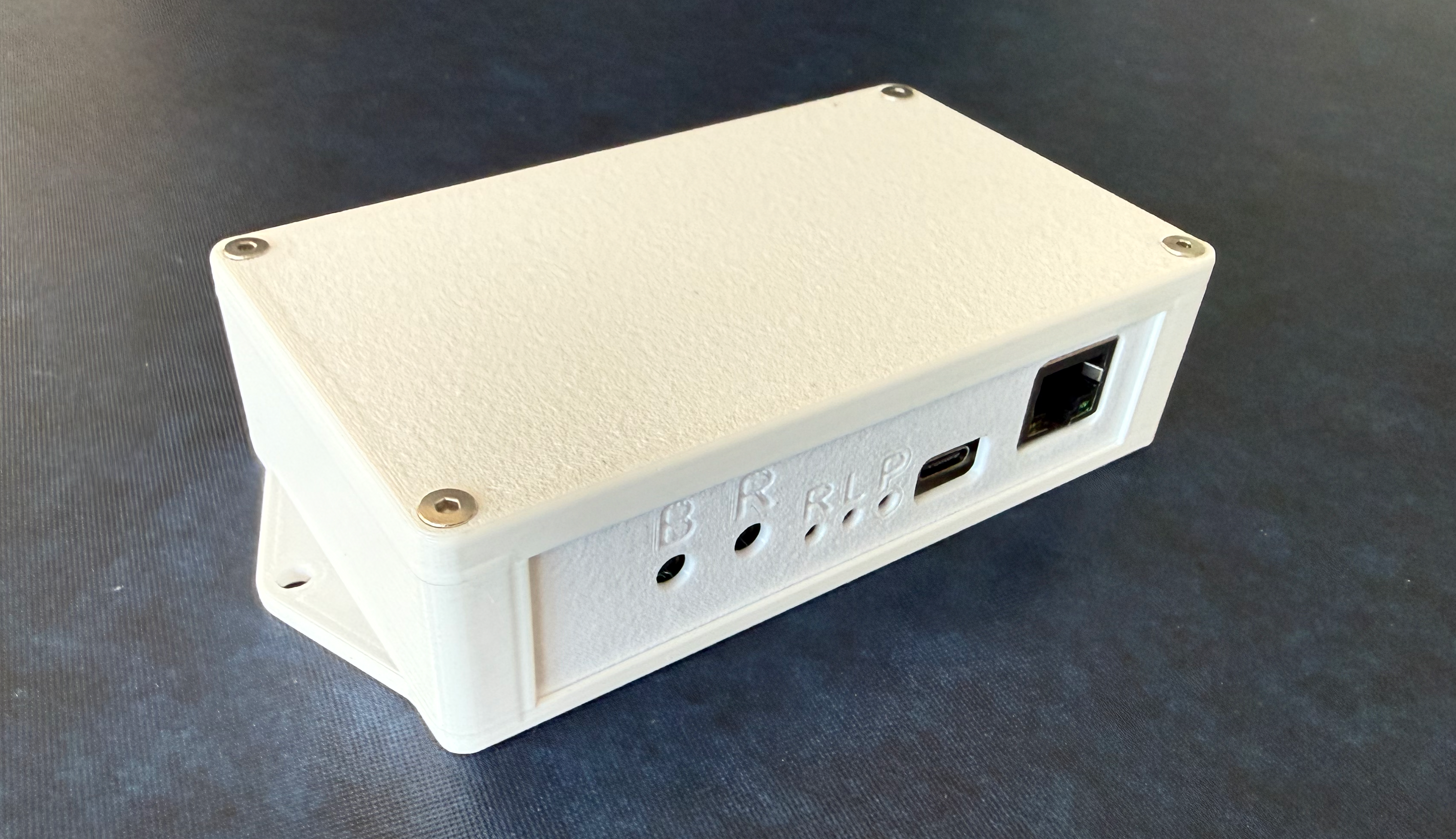
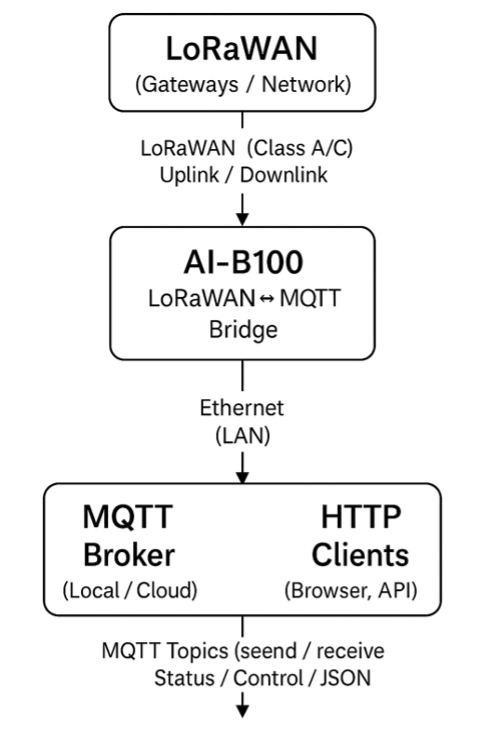
The AI‑B100 is an industrial LoRaWAN-to-MQTT/HTTP bridge that connects LoRaWAN end devices to your application over a standard Ethernet network. It supports Class A and Class C LoRaWAN operation and delivers data to your application via MQTT or HTTP callbacks. Configuration and diagnostics are available through an integrated web interface.
Key Features
- LoRaWAN 1.0.4 and 1.1.0 Class A/C support
- MQTT uplink and downlink bridging
- Integrated Ethernet web interface for configuration
- OTA firmware updates via external WiFi (WPA2)
- External trigger input (10–48 V DC)
- JSON‑based HTTP API
- Hardware watchdog and configurable safety timeout
- Automatic or manual data rate control (ADR)
- Binary and ASCII payload support
Revision History
| Version | Date | Description |
|---|---|---|
| 1.9.5 | 2026-05-11 | GPS and Info pages added; companion API manuals added |
| 1.8 | 2026-02-19 | HTTP API and support for hardware 1.3 |
| 1.7.6 | 2025-11-02 | LoRaWAN Class C support |
| 1.6 | 2025-06-17 | OTA for updates |
Hardware
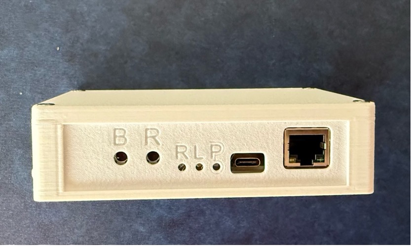
Buttons and LEDs
| Item | Function |
|---|---|
| Button B | BOOT / DHCP Toggle / Factory Reset |
| Button R | Hardware Reset |
| LED R | RF — LoRaWAN activity |
| LED L | LAN — LAN activity |
| LED P | PWR — Power |
Size
| Dimension | Value |
|---|---|
| Length | 139 mm |
| Width | 70 mm |
| Height | 33 mm |
| Mounting holes | 130 mm |
Buttons
Reset restarts the AI-B100.
Boot is used for two functions: Factory Reset and DHCP Toggle.
When the Boot button is held during reset or power‑up, the AI‑B100 enters Software Update Mode, where it awaits a firmware upload via USB. This mode can be exited by performing a reset or power cycle.
If the Boot button is pressed after both LEDs begin blinking, two distinct modes are available depending on the duration of the press:
- 3 seconds — DHCP Toggle
- 10 seconds — Factory Reset: The EUI and keys will revert to the values indicated on the device label.
Power Input
The AI-B100 can be powered by:
- USB-C
- External 5 V via a plug on the side of the box (Hardware revision 1.3)
- PoE (optional)
External Trig Input
A connector located at the rear of the box is available for external signal integration. The accepted voltage range is 10–48 V DC at 2 mA. Any change in the signal will initiate an MQTT message. The status can be retrieved via JSON status messages through an HTTP request.
LED Indicators
There are 3 LED indicators on the box:
Power indicates if power is connected or not.
Hardware revision 1.2 is constant on red.
Hardware revision 1.3:
- Green = OK
- Red = Failure condition (Factory Reset may be required)
LoRaWAN Activity indicates status of the connection and communication.
| Pattern | Meaning |
|---|---|
| Off | Not a valid state |
| 75 ms On, 75 ms Off | LoRaWAN failed to connect |
| 500 ms On, 500 ms Off | LoRaWAN trying to connect |
| 1500 ms Off, 50 ms On | LoRaWAN connected but no activity |
| 30 ms On, 30 ms Off | LoRaWAN transceiver active RX or TX |
| On | Not a valid state |
LAN Activity indicates the status of the Ethernet and MQTT connections. The LED blinks green when DHCP is enabled and blue when a fixed IP address is configured.
| Pattern | Meaning |
|---|---|
| Off | Not a valid state |
| 500 ms On, 500 ms Off | LAN and MQTT trying to connect |
| 75 ms On, 75 ms Off | LAN or MQTT settings are incorrect |
| 1500 ms Off, 50 ms On | MQTT broker connected or waiting for HTTP request |
| 30 ms On, 30 ms Off | MQTT active RX or TX, or HTTP request in progress |
| On | Not a valid state |
Safety Timeout
The AI-B100 is programmed to initiate a reboot if it does not receive messages through MQTT, HTTP, or LoRaWAN within a designated time. This duration can be configured on the home page; the default timeout is set to 10,080 minutes, equivalent to seven days. Set to 0 to disable.
LoRaWAN
The AI-B100 conforms to the LoRaWAN specifications as described by The Things Network:
- LoRaWAN Specification 1.1.0 Class A and Class C — RP001 Regional Parameters 1.1
- LoRaWAN Specifications 1.04 Class A and Class C — RP002 Regional Parameters 1.04
Users are responsible for ensuring that airtime usage complies with local regulations and that all activities adhere to fair usage policies. Each transmission occupies a share of the available radio spectrum, and LoRaWAN networks enforce a duty cycle limit — the device must remain silent for a minimum period after each transmission. Sending too frequently, or at a low data rate that requires long air times, can exhaust the available duty cycle and cause transmissions to be blocked.
More information: www.thethingsnetwork.org/docs/lorawan/
Regional parameters: www.thethingsnetwork.org/docs/lorawan/regional-parameters/eu868/
Data Rates
The AI-B100 is compatible with Data Rates 0 through 5 as detailed in the table below. A lower data rate combined with a higher spreading factor extends the range of LoRaWAN communication, but also increases airtime, which limits the volume of data that can be transmitted and increases duty cycle consumption.
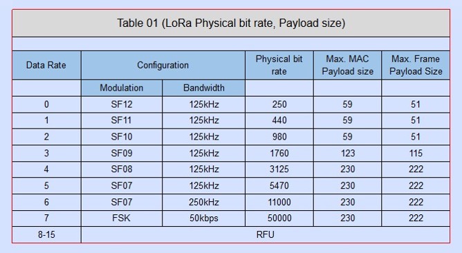
The Data Rate/Spreading Factor may be adjusted prior to transmitting a message. If the payload size exceeds the specified limit for the current data rate, an error message will be generated.
Confirmed uplink messages should be used only when guaranteed delivery is required, as they increase network load and may impact gateway duty‑cycle availability.
In LoRaWAN deployments, gateways are typically fewer than end devices; consequently, frequent transmission of confirmed uplinks from multiple devices may lead to excessive consumption of the gateway's duty cycle.
Device EUI
The LoRaWAN Device EUI utilizes a globally unique IEEE EUI number. To guarantee uniqueness, this identifier is derived from the ESP32-S3 chip, which contains a preprogrammed 64-bit EUI number. This number is assigned to Espressif, and any searches will identify the device as an Espressif product. By default, the Dev EUI is populated with the factory-built EUI; however, it can be overwritten if an alternative EUI is required.
Join EUI, AppKey and NwkKey
The Join EUI, AppKey, and NwkKey are prepopulated and available on the LoRaWAN settings page. While NwkKey is not required for LoRaWAN 1.0.4, it must still be entered. Leave the default value when using 1.0.4.
Status Codes
| Code | Meaning |
|---|---|
| 0 | LoRaWAN Status OK |
| 1 | Restarted — Ready to Join |
| 2 | LoRaWAN no payload |
| 3 | LoRaWAN payload too long |
| 4 | LoRaWAN could not join network |
| 5 | Restarted — Auto join enabled |
| 6 | LoRaWAN unknown error |
| 7 | LoRaWAN Joined |
| 8 | LoRaWAN payload received |
| 9 | LoRaWAN payload sent |
| 10 | LoRaWAN payload sent and confirmed |
| 11 | LoRaWAN payload not confirmed |
| 12 | LoRaWAN heartbeat |
| 13 | Duty cycle active — uplink blocked |
| 14 | LoRaWAN lost connection |
| 15 | LoRaWAN invalid port number |
| 16 | LoRaWAN uplink failed |
| 17 | LoRaWAN parameter error |
| 18 | LoRaWAN not joined |
| 19 | LoRaWAN parameter updated |
Getting Started
Follow these steps the first time you set up the AI‑B100.
Step 1 — Connect the hardware
Connect the AI‑B100 to your network with a standard Ethernet cable. Power the unit via USB‑C, PoE, or the external 5 V connector (HW 1.3). Both the Power LED and the LAN LED should begin blinking within a few seconds.
Step 2 — Find the IP address
By default, the AI‑B100 obtains an IP address from your DHCP server. Check your router or DHCP server's lease table to find the assigned address. If DHCP is not available, hold the Boot button for 3 seconds after startup to toggle to a fixed IP address (the default static IP is printed on the device label).
Step 3 — Open the web interface
Open a web browser and navigate to http://<ip-address>. The home page displays the current settings and lets you configure the gateway. Work through the configuration pages described in the Configuration section to enter your LoRaWAN credentials, network settings, and MQTT or HTTP callback details.
Step 4 — Register on your LoRaWAN network server
Before the AI‑B100 can join a LoRaWAN network, the device must be registered on your network server (for example The Things Network). You will need the Device EUI, Join EUI, and AppKey shown on the LoRaWAN Settings page. Enter the same credentials on the network server.
Step 5 — Join and send
Once credentials are saved, trigger a join from the web interface or via the MQTT or HTTP API. The LoRaWAN LED will change from a fast blink (trying to join) to a slow pulse (connected) when the join succeeds. The gateway is then ready to receive uplink commands from your application.
For detailed integration instructions, see the companion documents listed in Related Documents.
Configuration
The AI‑B100 is configured through its integrated web interface. Open a web browser and navigate to the gateway's IP address to access the configuration pages. Some settings take effect immediately; others require a restart — each page notes which apply.
Home Page
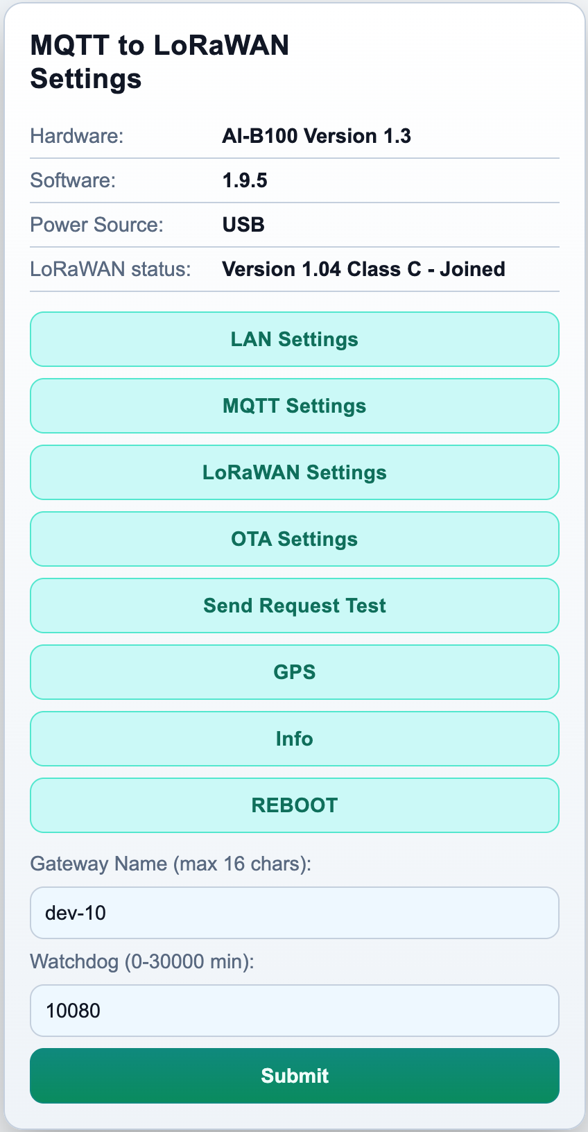
The home page is the main settings page and the first page shown when you open the web interface. It groups the most frequently used settings in one place.
Gateway name identifies this unit in MQTT payloads, HTTP callback responses, and in the $name$ tag that can be embedded in topic and path strings. Use a short descriptive name such as warehouse-01 when you have more than one gateway on the same network. Takes effect after restart.
Watchdog timeout sets how long the AI‑B100 will wait without any MQTT, HTTP, or LoRaWAN activity before automatically rebooting. The default is 10,080 minutes (seven days). Set to 0 to disable.
LAN Settings
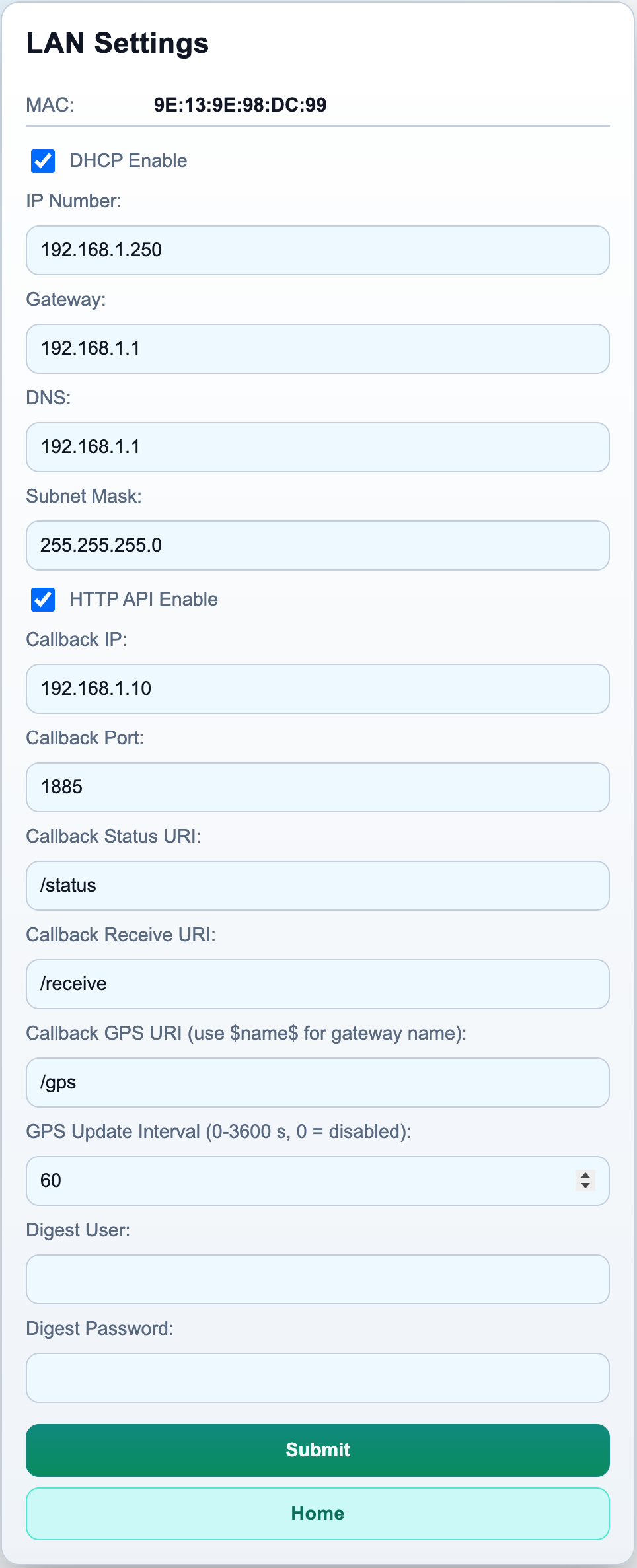
The LAN settings page controls how the AI‑B100 connects to your network. By default, DHCP is enabled and the gateway obtains its IP address automatically.
To assign a fixed IP address, disable DHCP and enter the IP address, subnet mask, default gateway, and DNS server for your network. A restart is required after any change to the LAN settings. After restarting with a static IP, connect your browser to the new address — the previous DHCP address will no longer respond.
If you need to return to DHCP and do not know the static IP, press the Boot button for 3 seconds after startup to toggle DHCP back on.
HTTP API enables or disables the JSON HTTP API used by external applications to send and receive LoRaWAN messages. Enable this if you are using the HTTP callback integration. Takes effect immediately.
Callback settings configure where the gateway sends its results — the IP address, port, and URL paths for status callbacks, receive callbacks, and optional GPS callbacks. You can embed $name$ in any path to route callbacks from multiple gateways to different URLs on the same server. These settings take effect immediately without a restart.
MQTT Settings
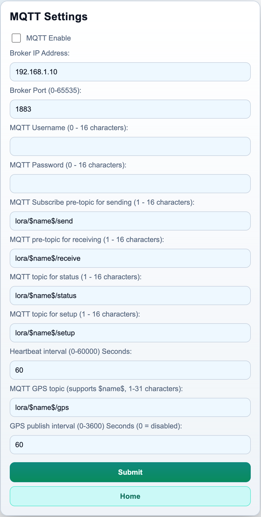
The MQTT settings page connects the gateway to an MQTT broker of your choice. When enabled, the gateway publishes LoRaWAN events to configurable topics and subscribes to topics for inbound commands.
Enable MQTT turns the MQTT client on or off. Requires a restart.
Broker address and port set the IP address and TCP port of your MQTT broker (standard port: 1883). Requires a restart.
Username and password are optional. Leave both empty if your broker does not require authentication. Requires a restart when changed.
Topics — five topic base strings are configured here:
- Status topic: the gateway publishes join results, send results, and heartbeats here.
- Receive topic: downlinks from the LoRaWAN network arrive here.
- Send topic: your application publishes uplink commands here.
- Setup topic: your application sends control commands (join, restart, data rate) here.
- GPS topic: the gateway publishes GPS position here at the configured interval.
You can embed $name$ in any topic string; the gateway replaces it with the configured gateway name at startup. All topic changes require a restart.
Heartbeat interval sets how often (in seconds) the gateway publishes a keep-alive message to the status topic. Set to 0 to disable. Takes effect immediately without a restart.
GPS interval sets how often (in seconds) the gateway publishes its GPS position to the GPS topic. Set to 0 to disable. Takes effect immediately without a restart.
For a full description of all MQTT topics and message formats, see the MQTT User Guide.
LoRaWAN Settings
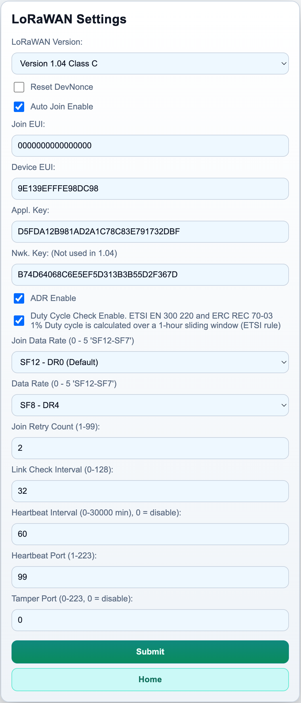
The LoRaWAN settings page configures the radio parameters and network credentials used to join and communicate over LoRaWAN.
LoRaWAN version selects the protocol version and device class: LoRaWAN 1.04 or 1.1, combined with Class A (low power, receive windows after each uplink only) or Class C (continuous receive, higher power consumption). Most deployments use Class A. Requires a restart.
Device EUI, Join EUI, and AppKey are the OTAA credentials that must match the registration on your LoRaWAN network server exactly. The Device EUI is pre-populated from the chip's factory identifier but can be overridden. Requires a restart after any change.
Network Key is only used with LoRaWAN 1.1. Leave the default value when using LoRaWAN 1.04. Requires a restart.
Auto join causes the gateway to begin joining automatically after every restart, without waiting for an explicit join command. Recommended for unattended deployments.
Join retry sets how many join attempts are made in each round before the gateway stops and waits for a manual join command.
Data rate (join) sets the spreading factor used during the join procedure. Data Rate 0 (SF12) has the longest range and is recommended for first-time setup or difficult RF environments.
Data rate sets the spreading factor used for uplinks after joining. Higher data rates allow larger payloads and shorter air times but have shorter range.
ADR (Adaptive Data Rate) lets the LoRaWAN network server automatically optimise the data rate over time. Enable for stationary installations; disable for mobile deployments.
Link check interval configures how often the gateway sends a signal-quality check to the network server (every N uplinks). The result is returned in the status response and includes the number of gateways that heard the uplink and the link margin. Set to 0 to disable.
LoRaWAN heartbeat — the gateway can send a periodic confirmed uplink to keep the session active when no application traffic is flowing. Set the interval in seconds and the LoRaWAN port to use. The payload is an incrementing counter. Set the interval to 0 to disable.
Over the Air (OTA) Update Settings
Over the air update (OTA) is done via connection to an external WiFi access point. That could be a mobile phone, a mobile internet unit, or any other wireless network that accepts a simple WPA2 connection and can provide internet access. If enabled, the gateway checks for an update immediately after each reboot.
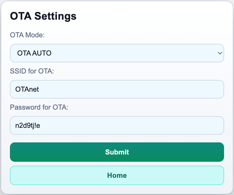
This page sets up the OTA mode, the Wi-Fi SSID, and the WPA2 password used only for OTA. These credentials are not used for any other purpose and are stored separately from other settings.
OTA Modes
| Mode | Description |
|---|---|
| OFF | OTA disabled |
| ONCE | Check once at next reboot; install if newer. Mode reverts to OFF after completion. |
| FORCE | Download and install regardless of version. Mode reverts to OFF after completion. |
| AUTO | Check at every reboot; install if newer |
Test Page
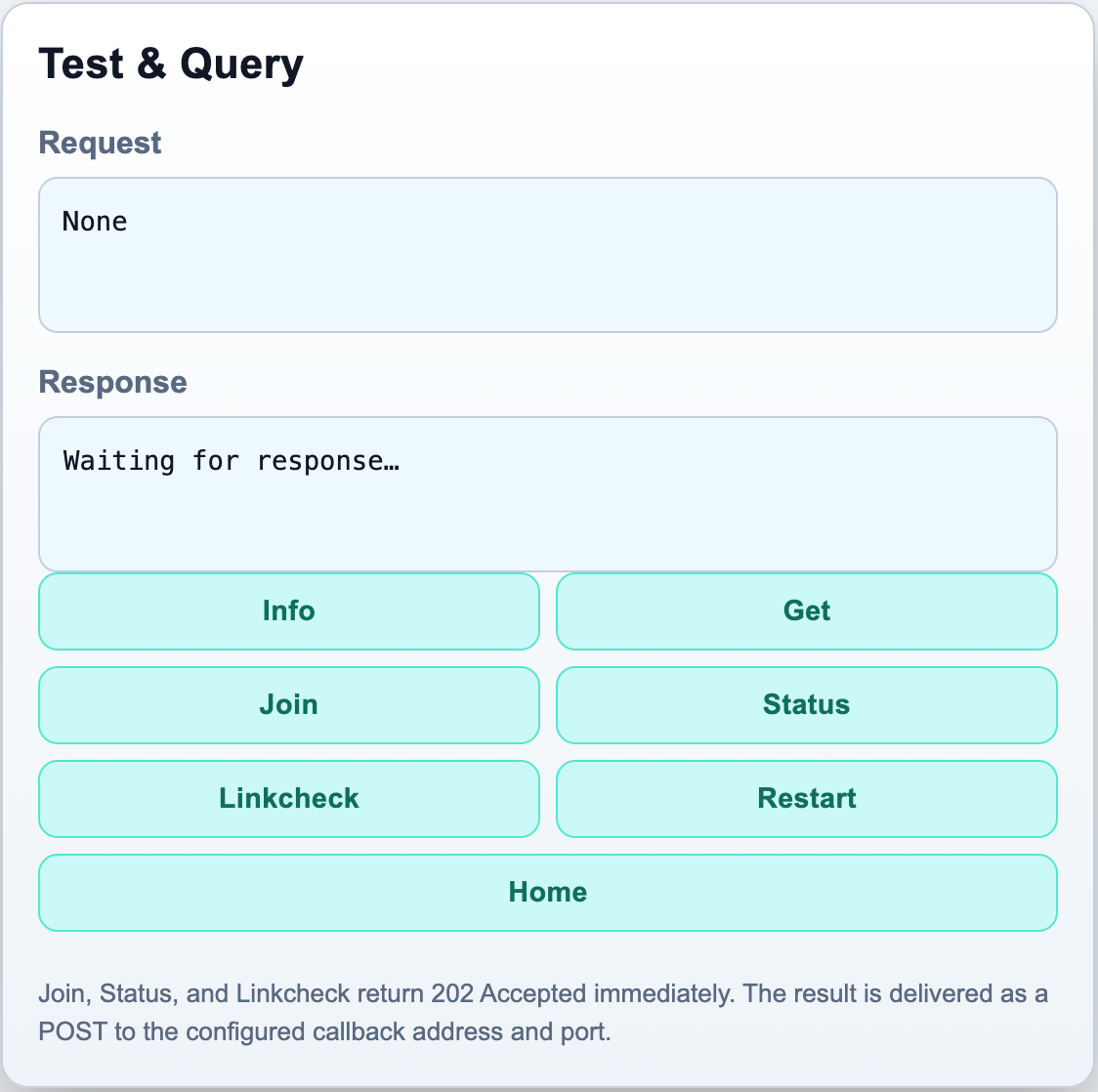
The Test page lets you send requests directly to the gateway's API from your browser without writing any code. Six buttons are available:
- Info — returns a JSON snapshot of the gateway state (firmware version, IP address, join state, and more).
- Get — returns all current settings as JSON.
- Join — triggers a LoRaWAN OTAA join attempt.
- Status — requests the current LoRaWAN status.
- Linkcheck — sends a LinkCheckReq to the LoRaWAN network and returns signal quality information.
- Restart — reboots the gateway.
Join, Status, and Linkcheck return 202 Accepted immediately. The result is delivered as a POST to the configured callback address and port, not shown on this page. Info and Get display their response directly in the Response box.
GPS Page
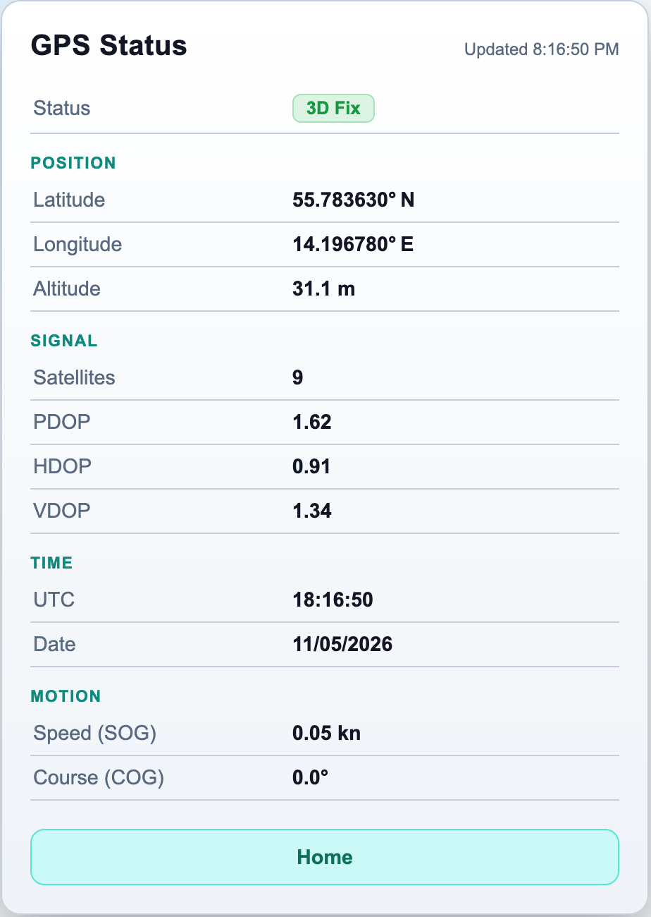
The GPS page displays the current status of the optional GPS module. It shows the fix quality (no module / no fix / 2D fix / 3D fix), the number of satellites in use, and — once a fix is acquired — the current coordinates, altitude, speed, and heading. Use this page to confirm that the GPS module is connected and has acquired a valid position before enabling GPS callbacks or MQTT GPS publishing.
Info Page
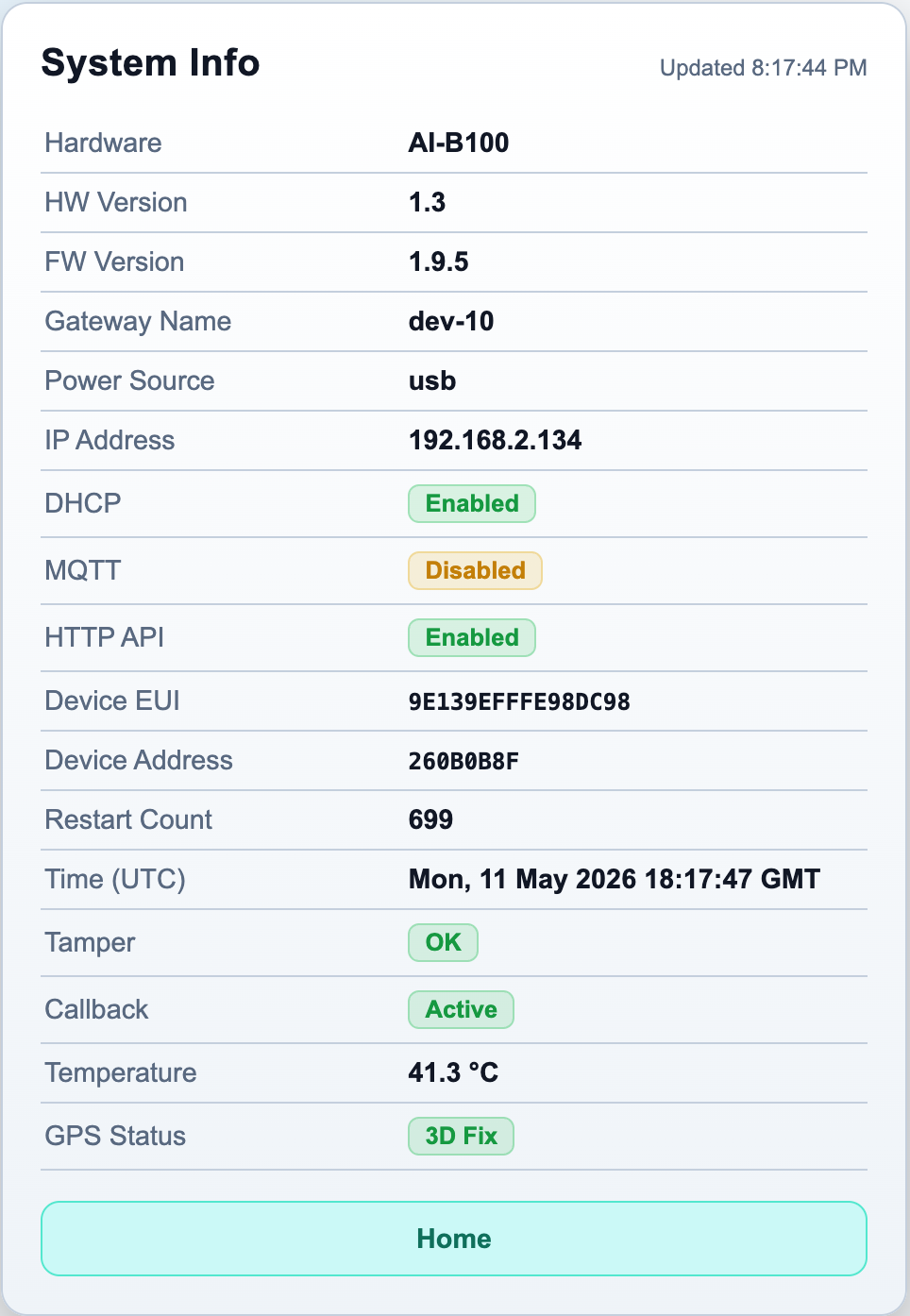
The Info page provides a read-only snapshot of the gateway's current state. It shows the firmware version, hardware revision, device EUI, current IP address, DHCP status, LoRaWAN join state (device address), and restart counter. On hardware revision 1.3, the board temperature is also shown. Use this page to verify that the correct firmware is installed and to confirm that the gateway is successfully joined to the LoRaWAN network.
Related Documents
The AI‑B100 documentation is distributed as a set of three documents. This manual covers hardware, LED indicators, first-time setup, configuration pages, and status codes. The two companion documents cover application integration:
MQTT User Guide
Describes how to connect the AI‑B100 to an MQTT broker and integrate it with your application using the publish/subscribe model. Covers all MQTT topics, message formats, status codes, typical lifecycle flows, and troubleshooting. Use this guide when your application connects to an MQTT broker rather than hosting a callback server.
HTTP API User Guide
Describes the request/response HTTP API for direct control of the gateway over Ethernet. Covers all endpoints, callback configuration, payload formats, Digest authentication, and troubleshooting. Use this guide when your application needs to send commands and receive results via HTTP callbacks.